QoS classification tools categorize packets by examining the contents of the frame, cell, and packet headers, whereas marking tools allow the QoS tool to change the packet headers for easier classification.
Most QoS tools classify traffic, which allows for each class of traffic to receive a different level of treatment from other traffic classes. These different types or classes of traffic are typically called service classes in QoS terminology.
To place voice and data traffic in separate queues, for example, you must use some form of classification to differentiate the two types of traffic and place the identified traffic in the proper queue.
Marking provides a way for QoS tools to change bits in the packet header to indicate the level of service this packet should receive from other QoS tools. For instance, you can use marking tools to change the marking in voice packets to ensure that a classification tool can differentiate a voice packet from a data packet.
Classification Tools
Class-Based Marking (CB-Marking) – CB Marking can also refer to access control lists (ACLs) to match packets, with packets permitted by an ACL being considered to match the logic used by CB Marking.
Classification with NBAR – NBAR classifies packets that are normally difficult to classify. For instance, some applications use dynamic port numbers, so a statically configured match command, looking for a particular UDP or TCP port number, simply could not classify the traffic. NBAR can look past the UDP and TCP header, and refer to the host name, URL, or MIME type in HTTP requests. This deeper examination of the packet contents is sometimes called deep packet inspection.
Marking
Marking involves setting some bits inside a data link or network layer header, with the goal of letting other devices’ QoS tools classify traffic based on the marked values.
QoS Marking Fields
The specific fields which can be used for QoS Marking are as follows:
| Field | Location | Length |
| IP Precedence (IPP) | IP Header | 3 bits |
| IP DSCP (Differentiated Services Code Point) | IP Header | 6 bits |
| DS Field (Differentiated Services) | IP Header | 1 Byte |
| ToS Byte (Type of Service) | IP Header | 1 Byte |
| CoS (Class of Service) | ISL and 802.1Q Header | 3 bits |
| Discard Eligible (DE) | Frame Relay Header | 1 bit |
| Cell Loss Priority (CLP) | ATM Cell Header | 1 bit |
| MPLS Experimental (EXP) | MPLS Header | 3 bits |
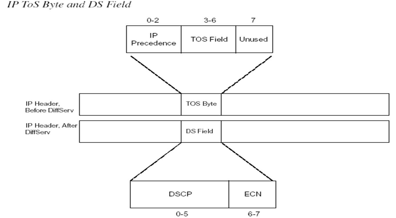
Legacy ToS Field
The IP header defined in RFC 791, includes a 1 Byte field called the “Type of Service (ToS). The ToS byte was intended to be used as a field to mark a packet for QoS. The ToS byte was further subdivided with the high-order 3 bits (0 through 2) defined as the IP Precedence (IPP) field. The bits 3 through 6 of the ToS Byte included flag fields that were toggled on (1) or off (0) to imply a particular QoS service. The final bit 7 was not defined in RFC791. The flags were not used very often. The main purpose of the ToS byte was to hold 3-bit IPP field.
                              -----------
                               IP Header
                              -----------

    0                   1                   2                   3
    0 1 2 3 4 5 6 7 8 9 0 1 2 3 4 5 6 7 8 9 0 1 2 3 4 5 6 7 8 9 0 1
   +-+-+-+-+-+-+-+-+-+-+-+-+-+-+-+-+-+-+-+-+-+-+-+-+-+-+-+-+-+-+-+-+
   |Version|  IHL  |Type of Service|          Total Length         |
   +-+-+-+-+-+-+-+-+-+-+-+-+-+-+-+-+-+-+-+-+-+-+-+-+-+-+-+-+-+-+-+-+
   |         Identification        |Flags|      Fragment Offset    |
   +-+-+-+-+-+-+-+-+-+-+-+-+-+-+-+-+-+-+-+-+-+-+-+-+-+-+-+-+-+-+-+-+
   |  Time to Live |    Protocol   |         Header Checksum       |
   +-+-+-+-+-+-+-+-+-+-+-+-+-+-+-+-+-+-+-+-+-+-+-+-+-+-+-+-+-+-+-+-+
   |                       Source Address                          |
   +-+-+-+-+-+-+-+-+-+-+-+-+-+-+-+-+-+-+-+-+-+-+-+-+-+-+-+-+-+-+-+-+
   |                    Destination Address                        |
   +-+-+-+-+-+-+-+-+-+-+-+-+-+-+-+-+-+-+-+-+-+-+-+-+-+-+-+-+-+-+-+-+
   |                    Options                    |    Padding    |
   +-+-+-+-+-+-+-+-+-+-+-+-+-+-+-+-+-+-+-+-+-+-+-+-+-+-+-+-+-+-+-+-+


          ----------------------------------------------------
           The Type of Service octet consists of three fields
          ----------------------------------------------------

                0     1     2     3     4     5     6     7
             +-----+-----+-----+-----+-----+-----+-----+-----+
             |                 |                       |     |
             |   PRECEDENCE    |          TOS          | MBZ |
             |                 |                       |     |
             +-----+-----+-----+-----+-----+-----+-----+-----+
First 3 bits (0 through 2) of ToS / IP Precedence
The Precedence field values imply that the larger the value, the more important the traffic.
| Field and Value (Decimal) | Binary Value | Name |
| Precedence 0 | 000 | Routine |
| Precedence 1 | 001 | Priority |
| Precedence 2 | 010 | Immediate |
| Precedence 3 | 011 | Flash |
| Precedence 4 | 100 | Flash Override |
| Precedence 5 | 101 | Critic/Critical/ECP |
| Precedence 6 | 110 | Internetwork Control |
| Precedence 7 | 111 | Network Control |
Next 4 bits (3 through 6) of TOS Values (RFC1349)
0000 — normal service (Default)
0001 — minimize monetary cost
0010 — maximize reliability
0100 — maximize throughput
1000 — minimize delay
The last field labeled “MBZ” was unused.
Modern DS Field (Differentiated Services)
The ToS field was updated by series of RFCs and the field itself was renamed as Differentiated Services (DS) field. IPP field of ToS byte was replaced with a 6-bit (high order bits 0 through 5) field called the Differentiated Services Code Point (DSCP) field. The RFC3168 defined the low order 2 bits (bits 6 through 7) of DS field for use with the QoS Explicit Congestion Notification (ECN) feature.
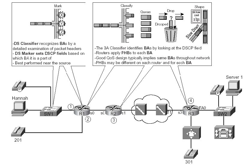
Differentiated Services Architectural Model
The differentiated services architecture is based on a simple model where traffic entering a network is classified and possibly conditioned at the boundaries of the network, and assigned to different behavior aggregates. Each behavior aggregate is identified by a single Differentiated Services Code Point (DSCP). Within the core of the network, packets are forwarded according to the per-hop behavior associated with the DSCP. RFC2475
Behavior Aggregates and Per-Hop Behavior
The Class Selector PHB and DSCP Values
The DS field is simply a redefinition of the original ToS Byte in the IP Header. IP Precedence (IPP) filed of ToS Byte overlaps with first 3-bits of DSCP field of DS field. Because of this overlap, RFC2475 defines a set of DSCP values and PHBs, called Class Selector (CS) PHBs, that provide backward compatibility with IPP.
| DSCP Class Selector Names | Binary Value of DSCP | Binary Value of IPP | IPP Field and Decimal Value | IPP Name |
| CS0 (Default) | 000000 | 000 | Precedence 0 | Routine |
| CS1 | 001000 | 001 | Precedence 1 | Priority |
| CS2 | 010000 | 010 | Precedence 2 | Immediate |
| CS3 | 011000 | 011 | Precedence 3 | Flash |
| CS4 | 100000 | 100 | Precedence 4 | Flash Override |
| CS5 | 101000 | 101 | Precedence 5 | Critic/Critical/ECP |
| CS6 | 110000 | 110 | Precedence 6 | Internetwork Control |
| CS7 | 111000 | 111 | Precedence 7 | Network Control |
Assured Forwarding PHB and DSCP Values
RFC 2597 defines four classes of Assured Forwarding (AF) PHB for queuing purpose, along with the three levels of drop probability inside each queue. To mark packets and distinguish into which of four queues a packet should be placed, along with one of three drop priorities inside each queue, the AF PHB defines 12 DSCP values and their meanings. The names of the AF DSCPs conform to the following format:
AFxy
where x implies one of the four queues (values 1-4) and y implies one of the three drop probabilities (values 1-3).
To convert from the AF name to the decimal equivalent, you can use a simple formula.
If you think of the AF values as AFxy, the formula is 8x + 2y = decimal value
For example, AF41 gives you a formula of (8 x 4) + (2 x 1) = 34
| Queue Class | Low Drop Probability Within Class | Medium Drop Probability Within Class | High Drop Probability Within Class |
| Name/Decimal/Binary | Name/Decimal/Binary | Name/Decimal/Binary | |
| Class 1 | AF11/10/001010 | AF12/12/001100 | AF13/14/001110 |
| Class 2 | AF21/18/010010 | AF22/20/010100 | AF23/22/010110 |
| Class 3 | AF31/26/011010 | AF32/32/011100 | AF33/30/011110 |
| Class 4 | AF41/34/100010 | AF42/42/100100 | AF43/38/100110 |
Commonly Used DSCP Values
| DSCP Value | Decimal Value | Meaning | Drop Probability | Equivalent IP Precedence Value |
| 101 110 | 46 | High Priority Expedited Forwarding (EF) | N/A | 101 – Critical |
| 000 000 | 0 | Best Effort | N/A | 000 – Routine |
| 001 010 | 10 | AF11 | Low | 001 – Priority |
| 001 100 | 12 | AF12 | Medium | 001 – Priority |
| 001 110 | 14 | AF13 | High | 001 – Priority |
| 010 010 | 18 | AF21 | Low | 010 – Immediate |
| 010 100 | 20 | AF22 | Medium | 010 – Immediate |
| 010 110 | 22 | AF23 | High | 010 – Immediate |
| 011 010 | 26 | AF31 | Low | 011 – Flash |
| 011 100 | 28 | AF32 | Medium | 011 – Flash |
| 011 110 | 30 | AF33 | High | 011 – Flash |
| 100 010 | 34 | AF41 | Low | 100 – Flash Override |
| 100 100 | 36 | AF42 | Medium | 100 – Flash Override |
| 100 110 | 38 | AF43 | High | 100 – Flash Override |
| 001 000 | 8 | CS1 | 1 | |
| 010 000 | 16 | CS2 | 2 | |
| 011 000 | 24 | CS3 | 3 | |
| 100 000 | 32 | CS4 | 4 | |
| 101 000 | 40 | CS5 | 5 | |
| 110 000 | 48 | CS6 | 6 | |
| 111 000 | 56 | CS7 | 7 |
The Expedited Forwarding PHB and DSCP Values
RFC 2598 defines the expedited forwarding per-hop behaviors. This RFC defines a very simple PHB (low latency, with a cap on bandwidth), and a single DSCP (EF) to represent it. Expedited forwarding simply states that a packet with the EF DSCP should minimize delay, jitter, and loss, up to a guaranteed bandwidth level for the class.
The expedited forwarding PHB uses a DSCP name of EF, whose binary value is 101110, with a decimal value of 46.
Ethernet LAN CoS (Class of Service)
The CoS (Class of Service) field only exists inside Ethernet frames when 802.1Q or Inter-Switch Link (ISL) trunking is used. The IEEE 802.1P standard actually defines the usage of the CoS bits inside the 802.1Q header. It is called CoS (Class of Service) in ISL header and “User-Priority bits” in 802.1Q tag field. But in general, it is referred as CoS field regardless of the type of trunking.

WAN Marking Fields
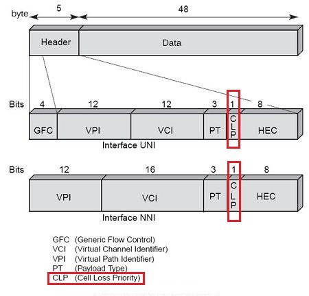
You can use single-bit fields in Frame Relay and ATM networks to mark a frame or cell for Layer 2 QoS. Frame Relay defines the discard eligibility (DE) bit, and ATM defines the cell loss priority (CLP) bit. The general idea is that when a device, typically a WAN switch, experiences congestion, it needs to discard some frames or cells. If a frame or cell has the DE or CLP bit set, respectively, the switch may choose to discard those frames or cells, and not discard other frames or cells. If the DE or CLP bit is set, there is no requirement that the Frame Relay and ATM switches react to it, just like there is no guarantee that an IP packet with DSCP EF will get special treatment by another router. It’s up to the owner of the Frame Relay or ATM switch to decide whether it will consider the DE and CLP bits, and how to react differently.
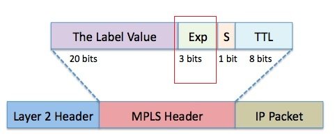
The MPLS Experimental bits comprise a 3-bit field that you can use to map IP precedence into an MPLS label.
Frame Relay Header

ATM Cell Header
MPLS Header
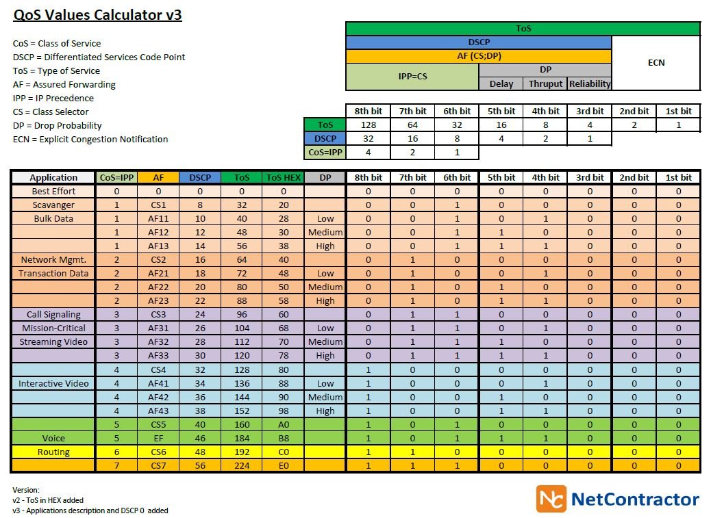
QoS Values Calculator
Reference: http://www.netcontractor.pl/blog/wp-content/uploads/2011/11/QoS-Values-Calculator-v3.jpg
Classification and Marking Design Choices
In summary, classification and marking tools classify packets based on a large number of different fields inside data link and network layer headers. Based on the classification, the tools then mark a field in a frame or packet header, with the goal that other QoS tools can more easily classify and perform specific QoS actions based on these marked fields. Among all the fields that can be marked, IP Precedence and DSCP, because they are part of the IP header, are the only fields that can be marked and carried from end to end in the network.
Cisco Recommended QoS Baseline
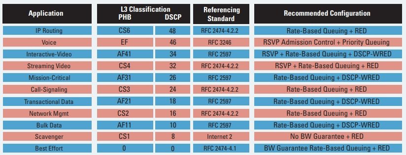
https://www.cisco.com/en/US/technologies/tk543/tk759/technologies_white_paper0900aecd80295a9b.pdf