Monthly Archives: March 2015

Packet Flow through Cisco ASA Firewall

Cisco ASA Packet Process Algorithm

The interface that receives the packet is called the ingress interface and the interface through which the packet exits is called the egress interface. When referring to the packet flow through any device, it can be easily simplified by looking at the task in terms of these two interfaces.

Here is a diagram of how the Cisco ASA processes the packet that it receives:

asa-packet-flow-2

Here are the individual steps in detail:

1. Packet is reached at the ingress interface.

2. Once the packet reaches the internal buffer of the interface, the input counter of the interface is incremented by one.

3. Cisco ASA will first verify if this is an existing connection by looking at its internal connection table details. If the packet flow matches an existing connection, then the access-control list (ACL) check is bypassed, and the packet is moved forward.

If packet flow does not match an existing connection, then TCP state is verified. If it is a SYN packet or UDP packet, then the connection counter is incremented by one and the packet is sent for an ACL check. If it is not a SYN packet, the packet is dropped and the event is logged.

4. The packet is processed as per the interface ACLs. It is verified in sequential order of the ACL entries and if it matches any of the ACL entries, it moves forward. Otherwise, the packet is dropped and the information is logged. The ACL hit count will be incremented by one when the packet matches the ACL entry.

5. The packet is verified for the translation rules. If a packet passes through this check, then a connection entry is created for this flow, and the packet moves forward. Otherwise, the packet is dropped and the information is logged.

6. The packet is subjected to an Inspection Check. This inspection verifies whether or not this specific packet flow is in compliance with the protocol. Cisco ASA has a built-in inspection engine that inspects each connection as per its pre-defined set of application-level functionalities. If it passed the inspection, it is moved forward. Otherwise, the packet is dropped and the information is logged.

Additional Security-Checks will be implemented if a CSC module is involved.

7. The IP header information is translated as per the NAT/PAT rule and checksums are updated accordingly. The packet is forwarded to AIP-SSM for IPS related security checks, when the AIP module is involved.

8. The packet is forwarded to the egress interface based on the translation rules. If no egress interface is specified in the translation rule, then the destination interface is decided based on global route lookup.

9. On the egress interface, the interface route lookup is performed. Remember, the egress interface is determined by the translation rule that will take the priority.

10. Once a Layer 3 route has been found and the next hop identified, Layer 2 resolution is performed. Layer 2 rewrite of MAC header happens at this stage.

11. The packet is transmitted on wire, and Interface counters increment on the egress interface.

Show Commands

Here are some useful commands that help in tracking the packet flow details at different stages of processing:

Show interface
Show conn
Show access-list
Show xlate
Show service-policy inspect
Show run static
Show run nat
Show run global
Show nat
Show route
Show arp

Syslog Messages

Syslog messages provide useful information about packet processing. Here are some example syslog messages for your reference:

Syslog message when there is no connection entry:

%ASA-6-106015: Deny TCP (no connection) from
IP_address/port to IP_address/port flags tcp_flags on interface
interface_name

Syslog message when the packet is denied by an access-list:

%ASA-4-106023: Deny protocol src
[interface_name:source_address/source_port] dst
interface_name:dest_address/dest_port by access_group
acl_ID

Syslog message when there is no translation rule is found:

%ASA-3-305005: No translation group found for protocol
src interface_name: source_address/source_port dst interface_name:
dest_address/dest_port

Syslog message when a packet is denied by Security Inspection:

%ASA-4-405104: H225 message received from
outside_address/outside_port to inside_address/inside_port before
SETUP

Syslog message when there is no route information:

%ASA-6-110003: Routing failed to locate next-hop for
protocol from src interface:src IP/src port to dest interface:dest IP/dest
port

JUNOS OSPF Configuration

We will discuss these topics in this session:

1. OSPF configuration
2. OSPF passive interface
3. OSPF Virtual Link
4. OSPF interface network type
5. OSPF interface cost manipulation
6. OSPF Authentication

This is the network topology for these configurations:

juniper-ospf

This is the initial configuration on these routers:

set version 10.1R1.8
set system host-name R1
set system root-authentication encrypted-password "$1$xWlYH6tk$VKHjArc1AcBtkzma6DOB9."
set system login user amolak uid 2000
set system login user amolak class super-user
set system login user amolak authentication encrypted-password "$1$avCx48qv$IoOMsiL/nUI1mDD6v4nJy0"
set system syslog user * any emergency
set system syslog file messages any notice
set system syslog file messages authorization info
set system syslog file interactive-commands interactive-commands any
set interfaces em0 unit 0 family inet address 1.1.12.1/24
set interfaces em1 unit 0 family inet address 1.1.21.1/24
set interfaces lo0 unit 0 family inet address 1.1.1.1/32
set routing-options router-id 1.1.1.1

set version 10.1R1.8
set system host-name R2
set system root-authentication encrypted-password "$1$xWlYH6tk$VKHjArc1AcBtkzma6DOB9."
set system login user amolak uid 2000
set system login user amolak class super-user
set system login user amolak authentication encrypted-password "$1$avCx48qv$IoOMsiL/nUI1mDD6v4nJy0"
set system syslog user * any emergency
set system syslog file messages any notice
set system syslog file messages authorization info
set system syslog file interactive-commands interactive-commands any
set interfaces em0 unit 0 family inet address 1.1.12.2/24
set interfaces em1 unit 0 family inet address 1.1.21.2/24
set interfaces em3 unit 0 family inet address 1.1.23.2/24
set interfaces lo0 unit 0 family inet address 2.2.2.2/32
set routing-options router-id 2.2.2.2

set version 10.1R1.8
set system host-name R3
set system root-authentication encrypted-password "$1$xWlYH6tk$VKHjArc1AcBtkzma6DOB9."
set system login user amolak uid 2000
set system login user amolak class super-user
set system login user amolak authentication encrypted-password "$1$avCx48qv$IoOMsiL/nUI1mDD6v4nJy0"
set system syslog user * any emergency
set system syslog file messages any notice
set system syslog file messages authorization info
set system syslog file interactive-commands interactive-commands any
set interfaces em0 unit 0 family inet address 1.1.34.3/24
set interfaces em3 unit 0 family inet address 1.1.23.3/24
set interfaces lo0 unit 0 family inet address 3.3.3.3/32
set routing-options router-id 3.3.3.3

set version 10.1R1.8
set system host-name R4
set system root-authentication encrypted-password "$1$xWlYH6tk$VKHjArc1AcBtkzma6DOB9."
set system login user amolak uid 2000
set system login user amolak class super-user
set system login user amolak authentication encrypted-password "$1$avCx48qv$IoOMsiL/nUI1mDD6v4nJy0"
set system syslog user * any emergency
set system syslog file messages any notice
set system syslog file messages authorization info
set system syslog file interactive-commands interactive-commands any
set interfaces em0 unit 0 family inet address 1.1.34.4/24
set interfaces lo0 unit 0 family inet address 4.4.4.4/32
set routing-options router-id 4.4.4.4

## Router-ID is already configured on all routers with below command.

    set routing-options router-id x.x.x.x

1. OSPF configuration

– Configure OSPF area on router interfaces as per drawing. Configure loopback interface as passive interface.

R1:

amolak@R1> configure 
Entering configuration mode

[edit]
amolak@R1# set protocols ospf area 0 interface em0.0 
amolak@R1# set protocols ospf area 0 interface em1.0 
amolak@R1# set protocols ospf area 0 interface lo0.0 passive 
amolak@R1# commit and-quit 

R2:

amolak@R2> configure 
Entering configuration mode

[edit]
amolak@R2# set protocols ospf area 0 interface em0.0 
amolak@R2# set protocols ospf area 0 interface em1.0    
amolak@R2# set protocols ospf area 0 interface lo0.0 passive 
amolak@R2# set protocols ospf area 1 interface em3.0 
amolak@R2# commit and-quit 

R3:

amolak@R3> configure 
Entering configuration mode

[edit]
amolak@R3# set protocols ospf area 1 interface em3.0 
amolak@R3# set protocols ospf area 2 interface em0.0 
amolak@R3# set protocols ospf area 1 interface lo0.0 passive 
amolak@R3# commit and-quit 

R4:

amolak@R4> configure 
Entering configuration mode

[edit]
amolak@R4# set protocols ospf area 2 interface em0.0 
amolak@R4# set protocols ospf area 2 interface lo0.0 passive 
amolak@R4# commit and-quit
Verification:

amolak@R1> show ospf interface    
Interface           State   Area            DR ID           BDR ID          Nbrs
em0.0               BDR     0.0.0.0         2.2.2.2         1.1.1.1            1
em1.0               BDR     0.0.0.0         2.2.2.2         1.1.1.1            1
lo0.0               DRother 0.0.0.0         0.0.0.0         0.0.0.0            0

amolak@R1> show ospf neighbor 
Address          Interface              State     ID               Pri  Dead
1.1.12.2         em0.0                  Full      2.2.2.2          128    34
1.1.21.2         em1.0                  Full      2.2.2.2          128    38

amolak@R1> show ospf database 

    OSPF database, Area 0.0.0.0
 Type       ID               Adv Rtr           Seq      Age  Opt  Cksum  Len 
Router  *1.1.1.1          1.1.1.1          0x80000005   130  0x22 0xd7da  60
Router   2.2.2.2          2.2.2.2          0x80000004   131  0x22 0x3b69  60
Network  1.1.12.2         2.2.2.2          0x80000002   131  0x22 0x26ee  32
Network  1.1.21.2         2.2.2.2          0x80000002   131  0x22 0xc249  32
Summary  1.1.23.0         2.2.2.2          0x80000002   166  0x22 0x3edb  28
Summary  3.3.3.3          2.2.2.2          0x80000001   102  0x22 0xcc5b  28

amolak@R1> show route protocol ospf 

inet.0: 9 destinations, 9 routes (9 active, 0 holddown, 0 hidden)
+ = Active Route, - = Last Active, * = Both

1.1.23.0/24        *[OSPF/10] 00:01:21, metric 2
                      to 1.1.12.2 via em0.0
                    > to 1.1.21.2 via em1.0
2.2.2.2/32         *[OSPF/10] 00:01:21, metric 1
                    > to 1.1.12.2 via em0.0
                      to 1.1.21.2 via em1.0
3.3.3.3/32         *[OSPF/10] 00:00:55, metric 2
                    > to 1.1.12.2 via em0.0
                      to 1.1.21.2 via em1.0
224.0.0.5/32       *[OSPF/10] 00:02:32, metric 1
                      MultiRecv

amolak@R2> show ospf interface    
Interface           State   Area            DR ID           BDR ID          Nbrs
em0.0               DR      0.0.0.0         2.2.2.2         1.1.1.1            1
em1.0               DR      0.0.0.0         2.2.2.2         1.1.1.1            1
lo0.0               DRother 0.0.0.0         0.0.0.0         0.0.0.0            0
em3.0               DR      0.0.0.1         2.2.2.2         3.3.3.3            1

amolak@R2> show ospf neighbor 
Address          Interface              State     ID               Pri  Dead
1.1.12.1         em0.0                  Full      1.1.1.1          128    33
1.1.21.1         em1.0                  Full      1.1.1.1          128    35
1.1.23.3         em3.0                  Full      3.3.3.3          128    35

amolak@R2> show ospf database 

    OSPF database, Area 0.0.0.0
 Type       ID               Adv Rtr           Seq      Age  Opt  Cksum  Len 
Router   1.1.1.1          1.1.1.1          0x80000005   135  0x22 0xd7da  60
Router  *2.2.2.2          2.2.2.2          0x80000004   134  0x22 0x3b69  60
Network *1.1.12.2         2.2.2.2          0x80000002   134  0x22 0x26ee  32
Network *1.1.21.2         2.2.2.2          0x80000002   134  0x22 0xc249  32
Summary *1.1.23.0         2.2.2.2          0x80000002   169  0x22 0x3edb  28
Summary *3.3.3.3          2.2.2.2          0x80000001   105  0x22 0xcc5b  28

    OSPF database, Area 0.0.0.1
 Type       ID               Adv Rtr           Seq      Age  Opt  Cksum  Len 
Router  *2.2.2.2          2.2.2.2          0x80000004   112  0x22 0xa246  36
Router   3.3.3.3          3.3.3.3          0x80000002   108  0x22 0xcef6  48
Network *1.1.23.2         2.2.2.2          0x80000001   112  0x22 0x13ef  32
Summary *1.1.1.1          2.2.2.2          0x80000001   129  0x22 0x2907  28
Summary *1.1.12.0         2.2.2.2          0x80000002   169  0x22 0xb76d  28
Summary *1.1.21.0         2.2.2.2          0x80000002   169  0x22 0x54c7  28
Summary  1.1.34.0         3.3.3.3          0x80000002   103  0x22 0xa664  28
Summary *2.2.2.2          2.2.2.2          0x80000002   169  0x22 0xee3d  28
Summary  4.4.4.4          3.3.3.3          0x80000001    64  0x22 0x809f  28

amolak@R2> show route protocol ospf 

inet.0: 10 destinations, 10 routes (10 active, 0 holddown, 0 hidden)
+ = Active Route, - = Last Active, * = Both

1.1.1.1/32         *[OSPF/10] 00:01:33, metric 1
                    > to 1.1.12.1 via em0.0
                      to 1.1.21.1 via em1.0
3.3.3.3/32         *[OSPF/10] 00:01:09, metric 1
                    > to 1.1.23.3 via em3.0
224.0.0.5/32       *[OSPF/10] 00:02:24, metric 1
                      MultiRecv

amolak@R3> show ospf interface 
Interface           State   Area            DR ID           BDR ID          Nbrs
em3.0               BDR     0.0.0.1         2.2.2.2         3.3.3.3            1
lo0.0               DRother 0.0.0.1         0.0.0.0         0.0.0.0            0
em0.0               DR      0.0.0.2         3.3.3.3         4.4.4.4            1

amolak@R3> show ospf neighbor     
Address          Interface              State     ID               Pri  Dead
1.1.23.2         em3.0                  Full      2.2.2.2          128    38
1.1.34.4         em0.0                  Full      4.4.4.4          128    39

amolak@R3> show ospf database 

    OSPF database, Area 0.0.0.1
 Type       ID               Adv Rtr           Seq      Age  Opt  Cksum  Len 
Router   2.2.2.2          2.2.2.2          0x80000004   131  0x22 0xa246  36
Router  *3.3.3.3          3.3.3.3          0x80000002   125  0x22 0xcef6  48
Network  1.1.23.2         2.2.2.2          0x80000001   131  0x22 0x13ef  32
Summary  1.1.1.1          2.2.2.2          0x80000001   148  0x22 0x2907  28
Summary  1.1.12.0         2.2.2.2          0x80000002   188  0x22 0xb76d  28
Summary  1.1.21.0         2.2.2.2          0x80000002   188  0x22 0x54c7  28
Summary *1.1.34.0         3.3.3.3          0x80000002   120  0x22 0xa664  28
Summary  2.2.2.2          2.2.2.2          0x80000002   188  0x22 0xee3d  28
Summary *4.4.4.4          3.3.3.3          0x80000001    80  0x22 0x809f  28

    OSPF database, Area 0.0.0.2
 Type       ID               Adv Rtr           Seq      Age  Opt  Cksum  Len 
Router  *3.3.3.3          3.3.3.3          0x80000004    85  0x22 0x6167  36
Router   4.4.4.4          4.4.4.4          0x80000002    84  0x22 0xdcc5  48
Network *1.1.34.3         3.3.3.3          0x80000002    85  0x22 0xc326  32
Summary *1.1.23.0         3.3.3.3          0x80000002   120  0x22 0x20f5  28
Summary *3.3.3.3          3.3.3.3          0x80000002   120  0x22 0xa281  28

amolak@R3> show route protocol ospf   

inet.0: 11 destinations, 11 routes (11 active, 0 holddown, 0 hidden)
+ = Active Route, - = Last Active, * = Both

1.1.1.1/32         *[OSPF/10] 00:01:15, metric 2
                    > to 1.1.23.2 via em3.0
1.1.12.0/24        *[OSPF/10] 00:01:15, metric 2
                    > to 1.1.23.2 via em3.0
1.1.21.0/24        *[OSPF/10] 00:01:15, metric 2
                    > to 1.1.23.2 via em3.0
2.2.2.2/32         *[OSPF/10] 00:01:15, metric 1
                    > to 1.1.23.2 via em3.0
4.4.4.4/32         *[OSPF/10] 00:00:35, metric 1
                    > to 1.1.34.4 via em0.0
224.0.0.5/32       *[OSPF/10] 00:01:25, metric 1
                      MultiRecv

amolak@R4> show ospf interface 
Interface           State   Area            DR ID           BDR ID          Nbrs
em0.0               BDR     0.0.0.2         3.3.3.3         4.4.4.4            1
lo0.0               DRother 0.0.0.2         0.0.0.0         0.0.0.0            0

amolak@R4> show ospf neighbor     
Address          Interface              State     ID               Pri  Dead
1.1.34.3         em0.0                  Full      3.3.3.3          128    36

amolak@R4> show ospf database 

    OSPF database, Area 0.0.0.2
 Type       ID               Adv Rtr           Seq      Age  Opt  Cksum  Len 
Router   3.3.3.3          3.3.3.3          0x80000004    96  0x22 0x6167  36
Router  *4.4.4.4          4.4.4.4          0x80000002    92  0x22 0xdcc5  48
Network  1.1.34.3         3.3.3.3          0x80000002    96  0x22 0xc326  32
Summary  1.1.23.0         3.3.3.3          0x80000002   131  0x22 0x20f5  28
Summary  3.3.3.3          3.3.3.3          0x80000002   131  0x22 0xa281  28

amolak@R4> show route protocol ospf 

inet.0: 6 destinations, 6 routes (6 active, 0 holddown, 0 hidden)
+ = Active Route, - = Last Active, * = Both

1.1.23.0/24        *[OSPF/10] 00:00:42, metric 2
                    > to 1.1.34.3 via em0.0
3.3.3.3/32         *[OSPF/10] 00:00:42, metric 1
                    > to 1.1.34.3 via em0.0
224.0.0.5/32       *[OSPF/10] 00:00:52, metric 1
                      MultiRecv

amolak@R1> ping 3.3.3.3 source 1.1.1.1 
PING 3.3.3.3 (3.3.3.3): 56 data bytes
64 bytes from 3.3.3.3: icmp_seq=0 ttl=63 time=0.856 ms
64 bytes from 3.3.3.3: icmp_seq=1 ttl=63 time=0.704 ms
^C
--- 3.3.3.3 ping statistics ---
2 packets transmitted, 2 packets received, 0% packet loss
round-trip min/avg/max/stddev = 0.704/0.780/0.856/0.076 ms

amolak@R1> ping 2.2.2.2 source 1.1.1.1    
PING 2.2.2.2 (2.2.2.2): 56 data bytes
64 bytes from 2.2.2.2: icmp_seq=0 ttl=64 time=0.552 ms
^C
--- 2.2.2.2 ping statistics ---
1 packets transmitted, 1 packets received, 0% packet loss
round-trip min/avg/max/stddev = 0.552/0.552/0.552/nan ms

3. OSPF Virtual Link

As per OSPF requirement, All Areas should be connected to backbone Area0. Here Area2 is not connected to Area0, because of this design issue Area0 and Area2 routers are not having each others advertised LSA in their ospf database. We need to create a virtual link to fix this issue.

– Configure OSPF virtual link between R2 and R3.

 amolak@R2> configure 
Entering configuration mode

[edit]
amolak@R2# set protocols ospf area 0 virtual-link neighbor-id 3.3.3.3 transit-area 1

amolak@R3> configure 
Entering configuration mode

[edit]
amolak@R3# set protocols ospf area 0 virtual-link neighbor-id 2.2.2.2 transit-area 1

## 'neighbor-id' is the peer router's router-id ##

Verification:

amolak@R2> show ospf interface    
Interface           State   Area            DR ID           BDR ID          Nbrs
em0.0               DR      0.0.0.0         2.2.2.2         1.1.1.1            1
em1.0               DR      0.0.0.0         2.2.2.2         1.1.1.1            1
lo0.0               DRother 0.0.0.0         0.0.0.0         0.0.0.0            0
vl-3.3.3.3          PtToPt  0.0.0.0         0.0.0.0         0.0.0.0            1
em3.0               DR      0.0.0.1         2.2.2.2         3.3.3.3            1

amolak@R2> show ospf neighbor     
Address          Interface              State     ID               Pri  Dead
1.1.12.1         em0.0                  Full      1.1.1.1          128    33
1.1.21.1         em1.0                  Full      1.1.1.1          128    34
1.1.23.3         vl-3.3.3.3             Full      3.3.3.3            0    32
1.1.23.3         em3.0                  Full      3.3.3.3          128    33

amolak@R3> show ospf interface    
Interface           State   Area            DR ID           BDR ID          Nbrs
em3.0               BDR     0.0.0.1         2.2.2.2         3.3.3.3            1
lo0.0               DRother 0.0.0.1         0.0.0.0         0.0.0.0            0
em0.0               DR      0.0.0.2         3.3.3.3         4.4.4.4            1
vl-2.2.2.2          PtToPt  0.0.0.0         0.0.0.0         0.0.0.0            1

amolak@R3> show ospf neighbor     
Address          Interface              State     ID               Pri  Dead
1.1.23.2         em3.0                  Full      2.2.2.2          128    33
1.1.34.4         em0.0                  Full      4.4.4.4          128    34
1.1.23.2         vl-2.2.2.2             Full      2.2.2.2            0    37

Now R3 is connected to Area0 via virtual-link and become ABR for Area0,Area1 and Area2. 
Area0 and Area2 router should have each others prefix in their databases.

amolak@R3> show ospf database 

    OSPF database, Area 0.0.0.0
 Type       ID               Adv Rtr           Seq      Age  Opt  Cksum  Len 
Router   1.1.1.1          1.1.1.1          0x80000005   414  0x22 0xd7da  60
Router   2.2.2.2          2.2.2.2          0x80000007    78  0x22 0x9dca  72
Router  *3.3.3.3          3.3.3.3          0x80000003    77  0x22 0xd51c  36
Network  1.1.12.2         2.2.2.2          0x80000002   413  0x22 0x26ee  32
Network  1.1.21.2         2.2.2.2          0x80000002   413  0x22 0xc249  32
Summary  1.1.23.0         2.2.2.2          0x80000002   448  0x22 0x3edb  28
Summary *1.1.23.0         3.3.3.3          0x80000001    77  0x22 0x22f4  28
Summary *1.1.34.0         3.3.3.3          0x80000001    77  0x22 0xa863  28
Summary  3.3.3.3          2.2.2.2          0x80000001   384  0x22 0xcc5b  28
Summary *3.3.3.3          3.3.3.3          0x80000001    77  0x22 0xa480  28
Summary *4.4.4.4          3.3.3.3          0x80000001    77  0x22 0x809f  28

    OSPF database, Area 0.0.0.1
 Type       ID               Adv Rtr           Seq      Age  Opt  Cksum  Len 
Router   2.2.2.2          2.2.2.2          0x80000006    78  0x22 0xaa38  36
Router  *3.3.3.3          3.3.3.3          0x80000004    77  0x22 0xd6e8  48
Network  1.1.23.2         2.2.2.2          0x80000001   393  0x22 0x13ef  32
Summary  1.1.1.1          2.2.2.2          0x80000001   410  0x22 0x2907  28
Summary  1.1.12.0         2.2.2.2          0x80000002   450  0x22 0xb76d  28
Summary  1.1.21.0         2.2.2.2          0x80000002   450  0x22 0x54c7  28
Summary *1.1.34.0         3.3.3.3          0x80000002   382  0x22 0xa664  28
Summary  2.2.2.2          2.2.2.2          0x80000002   450  0x22 0xee3d  28
Summary *4.4.4.4          3.3.3.3          0x80000001   342  0x22 0x809f  28

    OSPF database, Area 0.0.0.2
 Type       ID               Adv Rtr           Seq      Age  Opt  Cksum  Len 
Router  *3.3.3.3          3.3.3.3          0x80000005    77  0x22 0x5f68  36
Router   4.4.4.4          4.4.4.4          0x80000002   346  0x22 0xdcc5  48
Network *1.1.34.3         3.3.3.3          0x80000002   347  0x22 0xc326  32
Summary *1.1.1.1          3.3.3.3          0x80000001    77  0x22 0x1516  28
Summary *1.1.12.0         3.3.3.3          0x80000001    77  0x22 0xa57b  28
Summary *1.1.21.0         3.3.3.3          0x80000001    77  0x22 0x42d5  28
Summary *1.1.23.0         3.3.3.3          0x80000002   382  0x22 0x20f5  28
Summary *2.2.2.2          3.3.3.3          0x80000001    77  0x22 0xdc4b  28
Summary *3.3.3.3          3.3.3.3          0x80000002   382  0x22 0xa281  28

amolak@R4> show ospf database 

    OSPF database, Area 0.0.0.2
 Type       ID               Adv Rtr           Seq      Age  Opt  Cksum  Len 
Router   3.3.3.3          3.3.3.3          0x80000005    68  0x22 0x5f68  36
Router  *4.4.4.4          4.4.4.4          0x80000002   344  0x22 0xdcc5  48
Network  1.1.34.3         3.3.3.3          0x80000002   348  0x22 0xc326  32
Summary  1.1.1.1          3.3.3.3          0x80000001    68  0x22 0x1516  28
Summary  1.1.12.0         3.3.3.3          0x80000001    68  0x22 0xa57b  28
Summary  1.1.21.0         3.3.3.3          0x80000001    68  0x22 0x42d5  28
Summary  1.1.23.0         3.3.3.3          0x80000002   383  0x22 0x20f5  28
Summary  2.2.2.2          3.3.3.3          0x80000001    68  0x22 0xdc4b  28
Summary  3.3.3.3          3.3.3.3          0x80000002   383  0x22 0xa281  28

amolak@R4> show route protocol ospf   

inet.0: 10 destinations, 10 routes (10 active, 0 holddown, 0 hidden)
+ = Active Route, - = Last Active, * = Both

1.1.1.1/32         *[OSPF/10] 00:01:08, metric 3
                    > to 1.1.34.3 via em0.0
1.1.12.0/24        *[OSPF/10] 00:01:08, metric 3
                    > to 1.1.34.3 via em0.0
1.1.21.0/24        *[OSPF/10] 00:01:08, metric 3
                    > to 1.1.34.3 via em0.0
1.1.23.0/24        *[OSPF/10] 00:05:40, metric 2
                    > to 1.1.34.3 via em0.0
2.2.2.2/32         *[OSPF/10] 00:01:08, metric 2
                    > to 1.1.34.3 via em0.0
3.3.3.3/32         *[OSPF/10] 00:05:40, metric 1
                    > to 1.1.34.3 via em0.0
224.0.0.5/32       *[OSPF/10] 00:05:50, metric 1
                      MultiRecv

amolak@R1> show ospf database 

    OSPF database, Area 0.0.0.0
 Type       ID               Adv Rtr           Seq      Age  Opt  Cksum  Len 
Router  *1.1.1.1          1.1.1.1          0x80000005   402  0x22 0xd7da  60
Router   2.2.2.2          2.2.2.2          0x80000007    70  0x22 0x9dca  72
Router   3.3.3.3          3.3.3.3          0x80000003    71  0x22 0xd51c  36
Network  1.1.12.2         2.2.2.2          0x80000002   403  0x22 0x26ee  32
Network  1.1.21.2         2.2.2.2          0x80000002   403  0x22 0xc249  32
Summary  1.1.23.0         2.2.2.2          0x80000002   438  0x22 0x3edb  28
Summary  1.1.23.0         3.3.3.3          0x80000001    71  0x22 0x22f4  28
Summary  1.1.34.0         3.3.3.3          0x80000001    71  0x22 0xa863  28
Summary  3.3.3.3          2.2.2.2          0x80000001   374  0x22 0xcc5b  28
Summary  3.3.3.3          3.3.3.3          0x80000001    71  0x22 0xa480  28
Summary  4.4.4.4          3.3.3.3          0x80000001    71  0x22 0x809f  28

amolak@R1> show route protocol ospf        

inet.0: 11 destinations, 11 routes (11 active, 0 holddown, 0 hidden)
+ = Active Route, - = Last Active, * = Both

1.1.23.0/24        *[OSPF/10] 00:07:00, metric 2
                      to 1.1.12.2 via em0.0
                    > to 1.1.21.2 via em1.0
1.1.34.0/24        *[OSPF/10] 00:01:33, metric 3
                      to 1.1.12.2 via em0.0
                    > to 1.1.21.2 via em1.0
2.2.2.2/32         *[OSPF/10] 00:07:00, metric 1
                    > to 1.1.12.2 via em0.0
                      to 1.1.21.2 via em1.0
3.3.3.3/32         *[OSPF/10] 00:06:34, metric 2
                    > to 1.1.12.2 via em0.0
                      to 1.1.21.2 via em1.0
4.4.4.4/32         *[OSPF/10] 00:01:33, metric 3
                      to 1.1.12.2 via em0.0
                    > to 1.1.21.2 via em1.0
224.0.0.5/32       *[OSPF/10] 00:08:11, metric 1
                      MultiRecv

Let's check end to end connectivity.

amolak@R1> ping 4.4.4.4 source 1.1.1.1 
PING 4.4.4.4 (4.4.4.4): 56 data bytes
64 bytes from 4.4.4.4: icmp_seq=0 ttl=62 time=0.696 ms
64 bytes from 4.4.4.4: icmp_seq=1 ttl=62 time=0.816 ms
64 bytes from 4.4.4.4: icmp_seq=2 ttl=62 time=0.815 ms
^C
--- 4.4.4.4 ping statistics ---
3 packets transmitted, 3 packets received, 0% packet loss
round-trip min/avg/max/stddev = 0.696/0.776/0.816/0.056 ms

4. OSPF interface network type

All the links are actually connected between two routers only, i.e, point-to-point link. But ethernet interface has default ospf network type is LAN that requires DR/BDR election and LSA type 2 in the OSPF database.

– Configure interface type as point-to-point between R2 and R3.

Interface type before this configuration:

amolak@R3> show ospf interface em3.0 detail 
Interface           State   Area            DR ID           BDR ID          Nbrs
em3.0               DR      0.0.0.1         3.3.3.3         0.0.0.0            1
  Type: LAN, Address: 1.1.23.3, Mask: 255.255.255.0, MTU: 1500, Cost: 1
  DR addr: 1.1.23.3, Priority: 128
  Adj count: 0
  Hello: 10, Dead: 40, ReXmit: 5, Not Stub
  Auth type: None
  Protection type: None
  Topology default (ID 0) -> Cost: 1

amolak@R2> configure 
Entering configuration mode

[edit]
amolak@R2# set protocols ospf area 1 interface em3.0 interface-type p2p 
amolak@R2# commit and-quit 

amolak@R3> configure 
Entering configuration mode

[edit]
amolak@R3# set protocols ospf area 1 interface em3.0 interface-type p2p 
amolak@R3# commit and-quit 
commit complete
Exiting configuration mode

amolak@R3> show ospf interface em3.0 detail    
Interface           State   Area            DR ID           BDR ID          Nbrs
em3.0               PtToPt  0.0.0.1         0.0.0.0         0.0.0.0            1
  Type: P2P, Address: 1.1.23.3, Mask: 255.255.255.0, MTU: 1500, Cost: 1
  Adj count: 1
  Hello: 10, Dead: 40, ReXmit: 5, Not Stub
  Auth type: None
  Protection type: None
  Topology default (ID 0) -> Cost: 1

amolak@R3> show ospf interface   
Interface           State   Area            DR ID           BDR ID          Nbrs
em3.0               PtToPt  0.0.0.1         0.0.0.0         0.0.0.0            1
lo0.0               DRother 0.0.0.1         0.0.0.0         0.0.0.0            0
em0.0               DR      0.0.0.2         3.3.3.3         4.4.4.4            1
vl-2.2.2.2          PtToPt  0.0.0.0         0.0.0.0         0.0.0.0            1


5. OSPF interface cost manipulation

There are two equal cost paths on R1 to reach rest of the network. Change ospf cost on interface so that the interface em0 link should be prefer path and em1 should be backup path.

When evaluating the cost of individual network segments, OSPF evaluates the reference bandwidth. For any link faster than 100 Mbps, the default cost metric is 1. To control the cost of the network segment, you can modify the metric value on an individual interface.

amolak@R1> show ospf interface em0.0 detail 
Interface           State   Area            DR ID           BDR ID          Nbrs
em0.0               BDR     0.0.0.0         2.2.2.2         1.1.1.1            1
  Type: LAN, Address: 1.1.12.1, Mask: 255.255.255.0, MTU: 1500, Cost: 1
  DR addr: 1.1.12.2, BDR addr: 1.1.12.1, Priority: 128
  Adj count: 1
  Hello: 10, Dead: 40, ReXmit: 5, Not Stub
  Auth type: None
  Protection type: None
  Topology default (ID 0) -> Cost: 1

amolak@R1> show ospf interface em1.0 detail 
Interface           State   Area            DR ID           BDR ID          Nbrs
em1.0               BDR     0.0.0.0         2.2.2.2         1.1.1.1            1
  Type: LAN, Address: 1.1.21.1, Mask: 255.255.255.0, MTU: 1500, Cost: 1
  DR addr: 1.1.21.2, BDR addr: 1.1.21.1, Priority: 128
  Adj count: 1
  Hello: 10, Dead: 40, ReXmit: 5, Not Stub
  Auth type: None
  Protection type: None
  Topology default (ID 0) -> Cost: 1

Let's increase the cost of interface em1.0 to make it as less prefered path.

amolak@R1> configure 
Entering configuration mode

[edit]
amolak@R1# set protocols ospf area 0 interface em1.0 metric 2 
amolak@R1# commit and-quit 

amolak@R2> configure 
Entering configuration mode

[edit]
amolak@R2# set protocols ospf area 0 interface em1.0 metric 2 
amolak@R2# commit and-quit 

amolak@R1> show route 2.2.2.2 

inet.0: 11 destinations, 11 routes (11 active, 0 holddown, 0 hidden)
+ = Active Route, - = Last Active, * = Both

2.2.2.2/32         *[OSPF/10] 00:01:30, metric 1
                    > to 1.1.12.2 via em0.0

If em0.0 goes down.

amolak@R1> configure 
Entering configuration mode

[edit]
amolak@R1# set interfaces em0.0 disable 

[edit]
amolak@R1# commit 
commit complete

[edit]
amolak@R1# run show route 2.2.2.2 

inet.0: 11 destinations, 11 routes (11 active, 0 holddown, 0 hidden)
+ = Active Route, - = Last Active, * = Both

2.2.2.2/32         *[OSPF/10] 00:00:01, metric 2
                    > to 1.1.21.2 via em1.0

[edit]
amolak@R1# run ping 2.2.2.2 source 1.1.1.1 
PING 2.2.2.2 (2.2.2.2): 56 data bytes
64 bytes from 2.2.2.2: icmp_seq=0 ttl=64 time=0.521 ms
^C
--- 2.2.2.2 ping statistics ---
1 packets transmitted, 1 packets received, 0% packet loss
round-trip min/avg/max/stddev = 0.521/0.521/0.521/nan ms

[edit]
amolak@R1# delete interfaces em0.0 disable 

[edit]
amolak@R1# commit and-quit 
commit complete
Exiting configuration mode

6. OSPF Authentication

All OSPFv2 protocol exchanges can be authenticated to guarantee that only trusted routing devices participate in the autonomous system’s routing. By default, OSPFv2 authentication is disabled.

Simple authentication – Authenticates by using a plain-text password that is included in the transmitted packet. The receiving routing device uses an authentication key (password) to verify the packet. Simple authentication uses a plain-text password that is included in the transmitted packet. The receiving routing device uses an authentication key (password) to verify the packet. Plain-text passwords are not encrypted and might be subject to packet interception.

- Configure Simple Authentication between R3 and R4. Use password key '@SIMPLE'

amolak@R3> configure 
Entering configuration mode

[edit]
amolak@R3# set protocols ospf area 2 interface em0.0 authentication simple-password @SIMPLE
amolak@R3# commit and-quit 

amolak@R4> configure 
Entering configuration mode

[edit]
amolak@R4# set protocols ospf area 2 interface em0.0 authentication simple-password @SIMPLE    
amolak@R4# commit and-quit 

amolak@R3> show ospf interface em0.0 detail 
Interface           State   Area            DR ID           BDR ID          Nbrs
em0.0               BDR     0.0.0.2         4.4.4.4         3.3.3.3            1
  Type: LAN, Address: 1.1.34.3, Mask: 255.255.255.0, MTU: 1500, Cost: 1
  DR addr: 1.1.34.4, BDR addr: 1.1.34.3, Priority: 128
  Adj count: 1
  Hello: 10, Dead: 40, ReXmit: 5, Not Stub
  Auth type: Password
  Protection type: None
  Topology default (ID 0) -> Cost: 1

amolak@R4> show ospf interface em0.0 detail 
Interface           State   Area            DR ID           BDR ID          Nbrs
em0.0               DR      0.0.0.2         4.4.4.4         3.3.3.3            1
  Type: LAN, Address: 1.1.34.4, Mask: 255.255.255.0, MTU: 1500, Cost: 1
  DR addr: 1.1.34.4, BDR addr: 1.1.34.3, Priority: 128
  Adj count: 1
  Hello: 10, Dead: 40, ReXmit: 5, Not Stub
  Auth type: Password
  Protection type: None
  Topology default (ID 0) -> Cost: 1

MD5 authentication – Authenticates by using an encoded MD5 checksum that is included in the transmitted packet. The receiving routing device uses an authentication key (password) to verify the packet. MD5 authentication uses an encoded MD5 checksum that is included in the transmitted packet. The receiving routing device uses an authentication key (password) to verify the packet.

You define an MD5 key for each interface. If MD5 is enabled on an interface, that interface accepts routing updates only if MD5 authentication succeeds. Otherwise, updates are rejected. The routing device only accepts OSPFv2 packets sent using the same key identifier (ID) that is defined for that interface.

For increased security, you can configure multiple MD5 keys, each with a unique key ID, and set the date and time to switch to a new key. The receiver of the OSPF packet uses the ID to determine which key to use for authentication.

– Configure MD5 Authentication between R2 and R3.Use password key ‘@OSPFMD5′

amolak@R3> configure 
Entering configuration mode

[edit]
amolak@R3# set protocols ospf area 1 interface em3.0 authentication md5 ?
Possible completions:
  <key-id>             Key ID for MD5 authentication (0..255)
[edit]
amolak@R3# set protocols ospf area 1 interface em3.0 authentication md5 1 ?
Possible completions:
  key                  MD5 authentication key value
  start-time           Start time for key transmission (YYYY-MM-DD.HH:MM)
[edit]
amolak@R3# set protocols ospf area 1 interface em3.0 authentication md5 1 key @OSPFMD5 ?         
Possible completions:
  <[Enter]>            Execute this command
  start-time           Start time for key transmission (YYYY-MM-DD.HH:MM)
  |                    Pipe through a command
[edit]
amolak@R3# set protocols ospf area 1 interface em3.0 authentication md5 1 key @OSPFMD5    

[edit]
amolak@R3# commit and-quit 

amolak@R2> configure 
Entering configuration mode

[edit]
amolak@R2# set protocols ospf area 1 interface em3.0 authentication md5 1 key @OSPFMD5           

[edit]
amolak@R2# commit and-quit 

amolak@R2> show ospf interface em3.0 detail 
Interface           State   Area            DR ID           BDR ID          Nbrs
em3.0               PtToPt  0.0.0.1         0.0.0.0         0.0.0.0            1
  Type: P2P, Address: 1.1.23.2, Mask: 255.255.255.0, MTU: 1500, Cost: 1
  Adj count: 1
  Hello: 10, Dead: 40, ReXmit: 5, Not Stub
  Auth type: MD5, Active key ID: 1, Start time: 1970 Jan  1 00:00:00 UTC
  Protection type: None
  Topology default (ID 0) -> Cost: 1

amolak@R3> show ospf interface em3.0 detail 
Interface           State   Area            DR ID           BDR ID          Nbrs
em3.0               PtToPt  0.0.0.1         0.0.0.0         0.0.0.0            1
  Type: P2P, Address: 1.1.23.3, Mask: 255.255.255.0, MTU: 1500, Cost: 1
  Adj count: 1
  Hello: 10, Dead: 40, ReXmit: 5, Not Stub
  Auth type: MD5, Active key ID: 1, Start time: 1970 Jan  1 00:00:00 UTC
  Protection type: None
  Topology default (ID 0) -> Cost: 1

Here is the final configuration on all routers:

R1:

amolak@R1> show configuration 
## Last commit: 2014-05-11 09:19:56 UTC by amolak
version 10.1R1.8;
system {
    host-name R1;
    root-authentication {
        encrypted-password "$1$xWlYH6tk$VKHjArc1AcBtkzma6DOB9."; ## SECRET-DATA
    }
    login {
        user amolak {
            uid 2000;
            class super-user;
            authentication {
                encrypted-password "$1$avCx48qv$IoOMsiL/nUI1mDD6v4nJy0"; ## SECRET-DATA
            }
        }
    }
    syslog {
        user * {
            any emergency;
        }
        file messages {
            any notice;
            authorization info;         
        }
        file interactive-commands {
            interactive-commands any;
        }
    }
}
interfaces {
    em0 {
        unit 0 {
            family inet {
                address 1.1.12.1/24;
            }
        }
    }
    em1 {
        unit 0 {
            family inet {
                address 1.1.21.1/24;
            }
        }
    }
    lo0 {
        unit 0 {                        
            family inet {
                address 1.1.1.1/32;
            }
        }
    }
}
routing-options {
    router-id 1.1.1.1;
}
protocols {
    ospf {
        area 0.0.0.0 {
            interface lo0.0 {
                passive;
            }
            interface em0.0;
            interface em1.0 {
                metric 2;
            }
        }
    }
}

amolak@R1> 

R2:

amolak@R2> show configuration 
## Last commit: 2014-05-11 09:26:23 UTC by amolak
version 10.1R1.8;
system {
    host-name R2;
    root-authentication {
        encrypted-password "$1$xWlYH6tk$VKHjArc1AcBtkzma6DOB9."; ## SECRET-DATA
    }
    login {
        user amolak {
            uid 2000;
            class super-user;
            authentication {
                encrypted-password "$1$avCx48qv$IoOMsiL/nUI1mDD6v4nJy0"; ## SECRET-DATA
            }
        }
    }
    syslog {
        user * {
            any emergency;
        }
        file messages {
            any notice;
            authorization info;         
        }
        file interactive-commands {
            interactive-commands any;
        }
    }
}
interfaces {
    em0 {
        unit 0 {
            family inet {
                address 1.1.12.2/24;
            }
        }
    }
    em1 {
        unit 0 {
            family inet {
                address 1.1.21.2/24;
            }
        }
    }
    em3 {
        unit 0 {                        
            family inet {
                address 1.1.23.2/24;
            }
        }
    }
    lo0 {
        unit 0 {
            family inet {
                address 2.2.2.2/32;
            }
        }
    }
}
routing-options {
    router-id 2.2.2.2;
}
protocols {
    ospf {
        area 0.0.0.0 {
            virtual-link neighbor-id 3.3.3.3 transit-area 0.0.0.1;
            interface em0.0;
            interface em1.0 {
                metric 2;               
            }
            interface lo0.0 {
                passive;
            }
        }
        area 0.0.0.1 {
            interface em3.0 {
                interface-type p2p;
                authentication {
                    md5 1 key "$9$3Mtqn6CrlvL7dikTFnC0OEhSrWL"; ## SECRET-DATA
                }
            }
        }
    }
}

amolak@R2> 

R3:

amolak@R3> show configuration 
## Last commit: 2014-05-11 09:26:30 UTC by amolak
version 10.1R1.8;
system {
    host-name R3;
    root-authentication {
        encrypted-password "$1$xWlYH6tk$VKHjArc1AcBtkzma6DOB9."; ## SECRET-DATA
    }
    login {
        user amolak {
            uid 2000;
            class super-user;
            authentication {
                encrypted-password "$1$avCx48qv$IoOMsiL/nUI1mDD6v4nJy0"; ## SECRET-DATA
            }
        }
    }
    syslog {
        user * {
            any emergency;
        }
        file messages {
            any notice;
            authorization info;         
        }
        file interactive-commands {
            interactive-commands any;
        }
    }
}
interfaces {
    em0 {
        unit 0 {
            family inet {
                address 1.1.34.3/24;
            }
        }
    }
    em3 {
        unit 0 {
            family inet {
                address 1.1.23.3/24;
            }
        }
    }
    lo0 {
        unit 0 {                        
            family inet {
                address 3.3.3.3/32;
            }
        }
    }
}
routing-options {
    router-id 3.3.3.3;
}
protocols {
    ospf {
        area 0.0.0.1 {
            interface em3.0 {
                interface-type p2p;
                authentication {
                    md5 1 key "$9$NG-dwkqPQ3/ylL7-w4oUDik5Q"; ## SECRET-DATA
                }
            }
            interface lo0.0 {
                passive;
            }
        }
        area 0.0.0.2 {                  
            interface em0.0 {
                authentication {
                    simple-password "$9$8w8LXNbsgoJUz3hyrvXxbwY"; ## SECRET-DATA
                }
            }
        }
        area 0.0.0.0 {
            virtual-link neighbor-id 2.2.2.2 transit-area 0.0.0.1;
        }
    }
}

 amolak@R3> 

R4:

amolak@R4> show configuration 
## Last commit: 2014-05-11 09:26:59 UTC by amolak
version 10.1R1.8;
system {
    host-name R4;
    root-authentication {
        encrypted-password "$1$xWlYH6tk$VKHjArc1AcBtkzma6DOB9."; ## SECRET-DATA
    }
    login {
        user amolak {
            uid 2000;
            class super-user;
            authentication {
                encrypted-password "$1$avCx48qv$IoOMsiL/nUI1mDD6v4nJy0"; ## SECRET-DATA
            }
        }
    }
    syslog {
        user * {
            any emergency;
        }
        file messages {
            any notice;
            authorization info;         
        }
        file interactive-commands {
            interactive-commands any;
        }
    }
}
interfaces {
    em0 {
        unit 0 {
            family inet {
                address 1.1.34.4/24;
            }
        }
    }
    lo0 {
        unit 0 {
            family inet {
                address 4.4.4.4/32;
            }
        }
    }
}
routing-options {                       
    router-id 4.4.4.4;
}
protocols {
    ospf {
        area 0.0.0.2 {
            interface em0.0 {
                authentication {
                    simple-password "$9$61fb/9tO1Ecyebs.f5F9COBI"; ## SECRET-DATA
                }
            }
            interface lo0.0 {
                passive;
            }
        }
    }
}

 amolak@R4>

Day One with JUNOS

I have configured JunOS in GNS3. You can refer below link to simulate a JunOS device with GNS3.

http://muralirajanm.blogspot.in/2011/01/gns3.html

We will discuss these topics in this post:

1. First time login to JunOS device
2. User Account
3. Interface IP address configuration
4. Static Routing in JunOS
5. Floating Static route – Qualified-next-hop

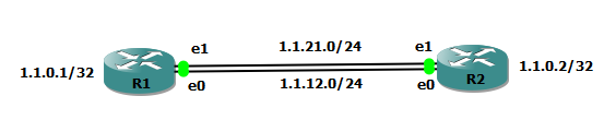
We will use this topology.

index

When you log in to a JunOS device, you are placed into one of two shells:

– C shell                                            %

– CLI in operational mode        user@router> (operational mode)
user@router# (configuration mode)

The root account or user is a predefined user name in JunOS. The root user is by default the administrator or super user, who has absolute permission to both configure and install software on a device. JunOS requires configuration of the root password before it accepts a commit. On a new device the root password must always be a part of the configuration submitted with your initial commit.

There is no default password for root account in initial configuration. You just need to type username as root and hit enter. When you login with root account, you will be placed in ‘C shell’. You have to type ‘cli’ to go to operational mode.

login: root

— JUNOS 10.1R1.8 built 2010-02-12 17:15:05 UTC

root@%

root@%

root@%

root@%

root@% cli

root>

Let’s configure hostname of device.

Type ‘configure’ in cli mode. It will change the prompt and place you in edit configuration mode.

root> configure

Entering configuration mode

[edit]

root#

[edit]

root# set system host-name R1

JunOS device does not use any of this configuration until you issue a commit command.

root# commit

[edit]

‘system’

Missing mandatory statement: ‘root-authentication’

error: commit failed: (missing statements)

[edit]

root#

Commit configuration is failed because root account must have a password before committing any configuration.

Let’s configure password for root account.

root# set system root-authentication plain-text-password
New password: *********
Retype new password: *********

[edit]

root# commit

commit complete

Let’s create other local user account. Class super-user is equivalent to privilege level 15 in Cisco IOS.

root@R1# set system login user amolak authentication plain-text-password

New password:

Retype new password:

[edit]

root@R1# set system login user amolak class super-user

[edit]

root@R1# commit

commit complete

[edit]

root@R1# exit

Exiting configuration mode

root@R1> exit

root@% exit

logout

R1 (ttyd0)

login: amolak

Password:

— JUNOS 10.1R1.8 built 2010-02-12 17:15:05 UTC

amolak@R1>

Now we will configure IP address on interface as per our topology.

– Each and every interface within the JunOS software requires at least one logical interface, called a unit. This is where all addressing and protocol information is configured.

– The inet protocol family supports IP version 4 (IPv4) packets.

amolak@R1# set interfaces em0 unit 0 family inet address 1.1.12.1/24

[edit]

amolak@R1# set interfaces em1 unit 0 family inet address 1.1.21.1/24

[edit]

amolak@R1# set interfaces lo0 unit 0 family inet address 1.1.0.1/32

[edit]

amolak@R1# commit

commit complete

[edit]

amolak@R1#

Similarly, configure R2.

amolak@R2> configure

Entering configuration mode

[edit]

amolak@R2# set interfaces em0 unit 0 family inet address 1.1.12.2/24

[edit]

amolak@R2# set interfaces em1 unit 0 family inet address 1.1.21.2/24

[edit]

amolak@R2# set interfaces lo0 unit 0 family inet address 1.1.0.2/32

[edit]

amolak@R2# commit

commit complete

[edit]

amolak@R2#

Lets verify the IP address on interfaces with show command. I have filtered interfaces only having IPv4 (family inet) address configured with “| match inet’.

amolak@R1> show interfaces terse | match inet
em0.0                   up    up   inet     1.1.12.1/24
em1.0                   up    up   inet     1.1.21.1/24
lo0.0                   up    up   inet     1.1.0.1             –> 0/0

amolak@R2# run show interfaces terse | match inet
em0.0                   up    up   inet     1.1.12.2/24
em1.0                   up    up   inet     1.1.21.2/24
lo0.0                   up    up   inet     1.1.0.2             –> 0/0

Verify the PING reachability.

amolak@R1> ping 1.1.12.2
PING 1.1.12.2 (1.1.12.2): 56 data bytes
64 bytes from 1.1.12.2: icmp_seq=0 ttl=64 time=23.090 ms
64 bytes from 1.1.12.2: icmp_seq=1 ttl=64 time=1.026 ms
^C
— 1.1.12.2 ping statistics —
2 packets transmitted, 2 packets received, 0% packet loss
round-trip min/avg/max/stddev = 1.026/12.058/23.090/11.032 ms

amolak@R1> ping 1.1.21.2
PING 1.1.21.2 (1.1.21.2): 56 data bytes
64 bytes from 1.1.21.2: icmp_seq=0 ttl=64 time=2.109 ms
64 bytes from 1.1.21.2: icmp_seq=1 ttl=64 time=0.719 ms
^C
— 1.1.21.2 ping statistics —
2 packets transmitted, 2 packets received, 0% packet loss
round-trip min/avg/max/stddev = 0.719/1.414/2.109/0.695 ms

Create a static route to reach Loopback interface IP address.

amolak@R1# set routing-options static route 1.1.0.2/32 next-hop 1.1.12.2

[edit]
amolak@R1# commit
commit complete

amolak@R2# set routing-options static route 1.1.0.1/32 next-hop 1.1.12.1

[edit]
amolak@R2# commit
commit complete

amolak@R1# exit
Exiting configuration mode

Verify PING to loopback interface IP.

amolak@R1> ping 1.1.0.2 source 1.1.0.1
PING 1.1.0.2 (1.1.0.2): 56 data bytes
64 bytes from 1.1.0.2: icmp_seq=0 ttl=64 time=0.650 ms
64 bytes from 1.1.0.2: icmp_seq=1 ttl=64 time=0.964 ms
64 bytes from 1.1.0.2: icmp_seq=2 ttl=64 time=0.780 ms
^C
— 1.1.0.2 ping statistics —
3 packets transmitted, 3 packets received, 0% packet loss
round-trip min/avg/max/stddev = 0.650/0.798/0.964/0.129 ms

amolak@R1>

amolak@R1> show route 1.1.0.2

inet.0: 6 destinations, 6 routes (6 active, 0 holddown, 0 hidden)
+ = Active Route, – = Last Active, * = Both

1.1.0.2/32         *[Static/5] 00:01:05
> to 1.1.12.2 via em0.0

By default, the static route has a default preference value of five. In general, the default properties assigned to a static route apply to all the next-hop addresses configured for the static route.  If, however, you want to configure two possible next-hop addresses for a particular route and have them treated differently, you can define one as a qualified next hop.

Qualified next hops allow you to associate one or more properties with a particular next-hop address. You can set an overall preference for a particular static route and then specify a different preference for the qualified next hop.

First, let’s try without qualified next-hop.

amolak@R1# set routing-options static route 1.1.0.2/32 next-hop 1.1.21.2 preference 10

[edit]
amolak@R1# commit
commit complete

[edit]
amolak@R1# exit
Exiting configuration mode

amolak@R1> show route 1.1.0.2

inet.0: 6 destinations, 6 routes (6 active, 0 holddown, 0 hidden)
+ = Active Route, – = Last Active, * = Both

1.1.0.2/32         *[Static/10] 00:00:03
to 1.1.12.2 via em0.0
> to 1.1.21.2 via em1.0

It has changed the preference value to 10 for both the next-hop addresses.

Rollback this configuration. We will discuss rollback feature in some other post. In short, JunOS keeps last fifty configurations (0-49). 0 is the current configuration state number.

amolak@R1# rollback 1
load complete

[edit]
amolak@R1# show | compare
[edit routing-options static route 1.1.0.2/32]
–    next-hop [ 1.1.12.2 1.1.21.2 ];
–    preference 10;
+    next-hop 1.1.12.2;

[edit]

‘show | compare’ compares the current configuration and last committed configuration and shows the differences.

Now lets add a second static route with qualified next-hop.

amolak@R1# set routing-options static route 1.1.0.2/32 qualified-next-hop 1.1.21.2 preference 10

[edit]
amolak@R1# commit
commit complete

The router is using the routes via next-hop marked with asterisk sign.

[edit]
amolak@R1# run show route 1.1.0.2

inet.0: 6 destinations, 7 routes (6 active, 0 holddown, 0 hidden)
+ = Active Route, – = Last Active, * = Both

1.1.0.2/32         *[Static/5] 00:01:10
> to 1.1.12.2 via em0.0
[Static/10] 00:00:03
> to 1.1.21.2 via em1.0

[edit]
amolak@R1#

If we disable (admin shutdown) the interface em0, the R2′s loopback interface IP is reachable via other next-hop now.

amolak@R1# set interfaces em0 disable

[edit]
amolak@R1# commit
commit complete

[edit]
amolak@R1# run show route 1.1.0.2

inet.0: 5 destinations, 5 routes (5 active, 0 holddown, 0 hidden)
+ = Active Route, – = Last Active, * = Both

1.1.0.2/32         *[Static/10] 00:01:00
> to 1.1.21.2 via em1.0

[edit]

Activate em0 interface.

amolak@R1# delete interfaces em0 disable

[edit]
amolak@R1# commit
commit complete

[edit]

amolak@R1# run show route 1.1.0.2

inet.0: 6 destinations, 7 routes (6 active, 0 holddown, 0 hidden)
+ = Active Route, – = Last Active, * = Both

1.1.0.2/32         *[Static/5] 00:00:06
> to 1.1.12.2 via em0.0
[Static/10] 00:01:23
> to 1.1.21.2 via em1.0

[edit]
amolak@R1#

Similarly, Configure R2.

[edit]
amolak@R2# set routing-options static route 1.1.0.1/32 qualified-next-hop 1.1.12.1 preference 10

[edit]
amolak@R2# commit
commit complete

[edit]
amolak@R2# run show route 1.1.0.1

inet.0: 6 destinations, 7 routes (6 active, 0 holddown, 0 hidden)
+ = Active Route, – = Last Active, * = Both

1.1.0.1/32         *[Static/5] 02:39:56
> to 1.1.12.1 via em0.0
[Static/10] 00:00:04
> to 1.1.12.1 via em0.0

[edit]
amolak@R2#

Final configuration on both routers.

amolak@R1> show configuration 
## Last commit: 2014-04-14 10:38:46 UTC by amolak
version 10.1R1.8;
system {
    host-name R1;
    root-authentication {
        encrypted-password "$1$EhyKZlJc$0WIdzQaoqwKSMBe92FcGy/"; ## SECRET-DATA
    }
    login {
        user amolak {
            uid 2000;
            class super-user;
            authentication {
                encrypted-password "$1$qNdbsrlc$Ha4nBWDuB6OdNpKzXIYZX1"; ## SECRET-DATA
            }
        }
    }
    syslog {
        user * {
            any emergency;
        }
        file messages {
            any notice;
            authorization info;         
        }
        file interactive-commands {
            interactive-commands any;
        }
    }
}
interfaces {
    em0 {
        unit 0 {
            family inet {
                address 1.1.12.1/24;
            }
        }
    }
    em1 {
        unit 0 {
            family inet {
                address 1.1.21.1/24;
            }
        }
    }
    lo0 {
        unit 0 {                        
            family inet {
                address 1.1.0.1/32;
            }
        }
    }
}
routing-options {
    static {
        route 1.1.0.2/32 {
            next-hop 1.1.12.2;
            qualified-next-hop 1.1.21.2 {
                preference 10;
            }
        }
    }
}

amolak@R1> 

amolak@R2> show configuration 
## Last commit: 2014-04-14 13:06:44 UTC by amolak
version 10.1R1.8;
system {
    host-name R2;
    root-authentication {
        encrypted-password "$1$2LOSmGiX$1ezYIzYSXOOfyvm15dz5S0"; ## SECRET-DATA
    }
    login {
        user amolak {
            uid 2000;
            class super-user;
            authentication {
                encrypted-password "$1$pqvVkBia$MxnHYNRelBmY9IQ8MR.rn/"; ## SECRET-DATA
            }
        }
    }
    syslog {
        user * {
            any emergency;
        }
        file messages {
            any notice;
            authorization info;         
        }
        file interactive-commands {
            interactive-commands any;
        }
    }
}
interfaces {
    em0 {
        unit 0 {
            family inet {
                address 1.1.12.2/24;
            }
        }
    }
    em1 {
        unit 0 {
            family inet {
                address 1.1.21.2/24;
            }
        }
    }
    lo0 {
        unit 0 {                        
            family inet {
                address 1.1.0.2/32;
            }
        }
    }
}
routing-options {
    static {
        route 1.1.0.1/32 {
            next-hop 1.1.12.1;
            qualified-next-hop 1.1.12.1 {
                preference 10;
            }
        }
    }
}

amolak@R2>

JUNOS Routing Tables

These are the different tables used in JUNOS.

Routing Table Name
Description
bgp.isovpn.0 Border Gateway Protocol (BGP) reachability information for ISO virtual private networks (VPNs).
bgp.l2vpn.0 BGP Layer 2 VPN routes.
bgp.l3vpn.0 BGP Layer 3 VPN routes.
bgp.rtarget.0 BGP route target information.
inet.0 Internet Protocol version 4 (IPv4) unicast routes.
inet.1 IP multicast routes. Each (S,G) pair in the network is placed into this table.
inet.2 IPv4 unicast routes. Used by IP multicast-enabled routing protocols to perform Reverse Path Forwarding (RPF).
inet.3 Accessed by BGP to use Multiprotocol Label Switching (MPLS) paths for forwarding traffic.
inet.4 Routes learned by the Multicast Source Discovery Protocol (MSDP).
inet6.0 Internet Protocol version 6 (IPv6) unicast routes.
inet6.3 Populated when the resolve-vpn statement is enabled to allow a router whose VPN control plane is undergoing a restart to continue to forward traffic while recovering its state from neighboring routers.
inetflow.0 Border Gateway Protocol (BGP) flow destination (firewall match criteria) information.
invpnflow.0 BGP flow destination (firewall match criteria) information within an RFC 2547 Layer 3 VPN.
iso.0 Intermediate System-to-Intermediate System (IS-IS) and End System-to-Intermediate System (ES-IS) routes.
l2circuit.0 Layer 2 circuit routes.
mpls.0 MPLS label-switched paths (LSPs). Contains a list of the next label-switched router in each LSP. Used by transit routers to route packets to the next router along an LSP.
<instance-name>.inet.0 Table that JUNOS software creates each time you configure an IPv4 unicast routing instance.
<instance-name>.inet.3 Table that JUNOS software creates for each BGP instance that is configured to use MPLS paths for forwarding traffic.
<instance-name>.inet6.0 Table that JUNOS software creates each time you configure an IPv6 unicast routing instance.
<instance-name>.inetflow.0 Table that JUNOS software creates each time you configure a routing instance. This table stores dynamic filtering information for BGP.
<instance-name>.iso.0 Table that JUNOS software creates each time you configure an IS-IS or ES-IS instance.
<instance-name>.mpls.0 Table that JUNOS software creates each time you configure MPLS LSPs.